I offer you a tutorial to make yourself a thermal camera for Android Smartphone or tablet.
You will need some electronic components (including the MLX90640 sensor), a printed circuit, a case and of course a soldering iron.
The Android application is FREE and available on Google play store :
https://play.google.com/store/apps/details?id=com.rienquepourlesyeux.thermalcamera
This application only require access to camera and file for save capture image. No datas are collected.
Files :
List of electronic components:
- MLX90640 BAB (55 degree angle BAB version).
It is a 32*24 pixel thermal camera.
This is the most expensive component, around 36 Euros. - A 0.42 inch ESP32S3 OLED created by 01Space (https://github.com/01Space/ESP32-S3-0.42OLED), count around 14 Dollards (You can find it on aliexpress for example).
I chose this microcontroller board because it is tiny and very powerful. - Two 1KOhms SMD resistors in 0805 version
- A 100nF SMD capacitor in 0805 version
- A capacitor of 100uf 6.3Volts
- Two 2mm*4mm screws
And that’s it! As you can see, very few electronic components.
You will also need to have a printed circuit made (for my part, I chose the company JCLPCB: https://jlcpcb.com/, cheap and very good).
for the box, I sent the STL file to a 3D printing company but if you have a 3D printer, you can do it yourself.
And, finally, to finish, a USB-C male/male adapter to connect the electronic box to the USB-C of the smartphone.
Once you have gathered all the components, you can start:

By default, the 01Space ESP32S3 module comes with a pre-loaded test program.
By connecting it via USB you will be able to see patterns and drawings on the display, this will allow you to validate its proper functioning.
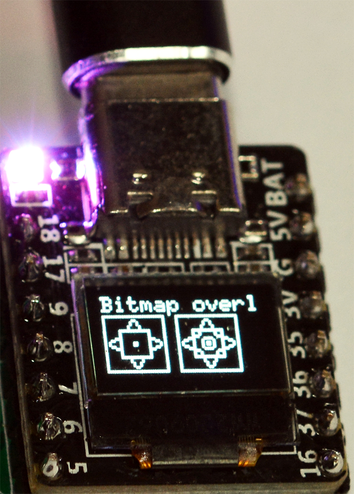
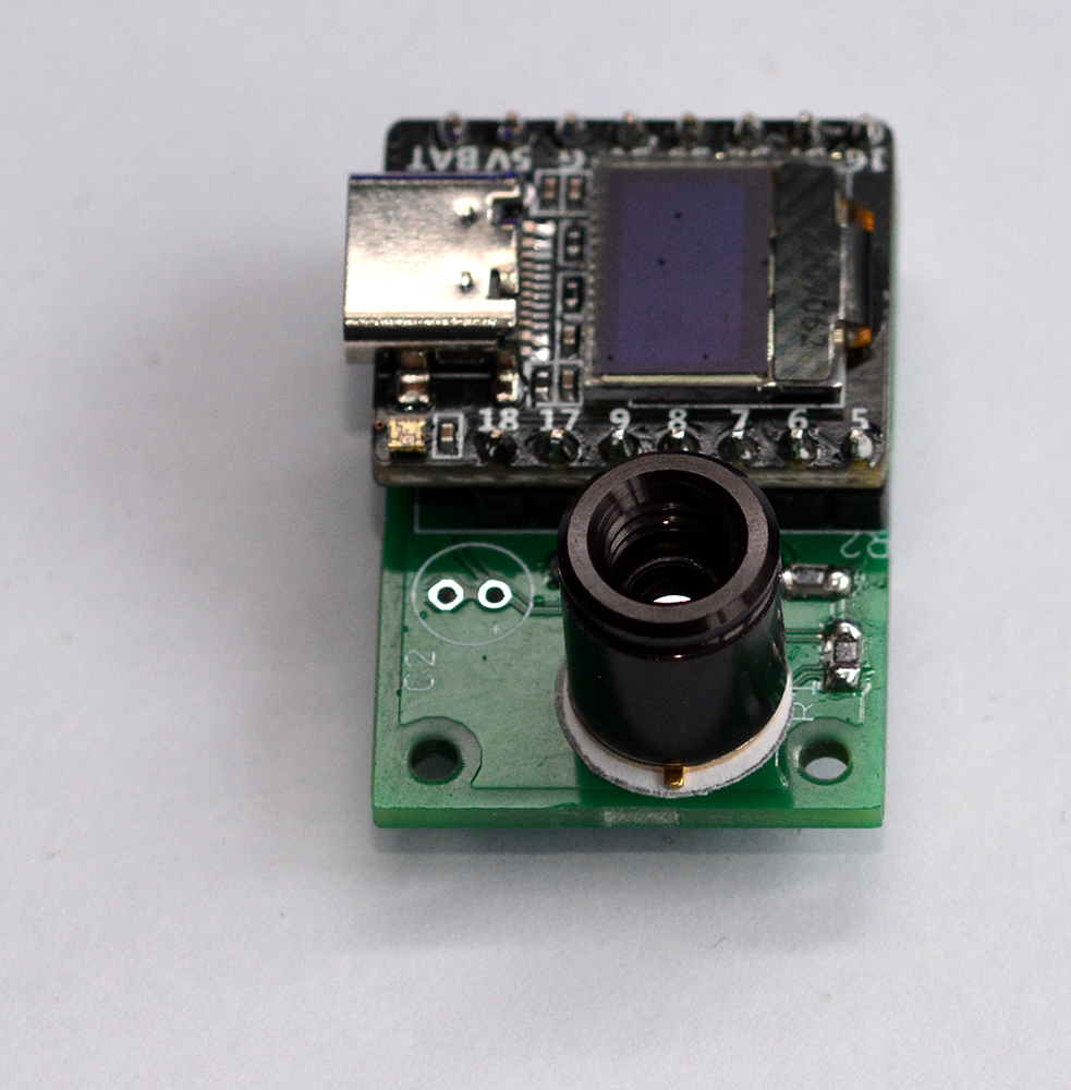
I advise you to start by downloading the thermal camera program in the ESP32S3 because as you can see in the photo below, the RESET and PROG buttons will be difficult to access if you need them during programming.
After programming and reset, it is possible that the white LED is still lit, in this case, perform another RESET, or disconnect and reconnect the module.
NB: I use the adafruit MLX90640 library to manage the thermal camera, but I modified this one so you will have to remember to update the files with the files contained in the ZIP file, if you want to compile the source code yourself via the arduino IDE for example.
Otherwise, use the ZIP easy upload program for ESP32S3 instead :
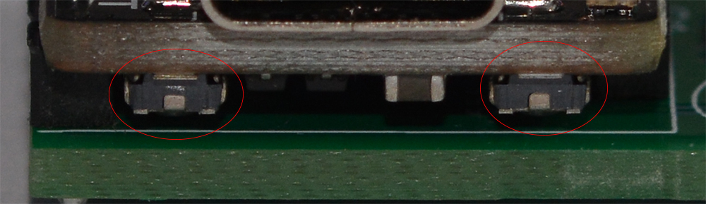
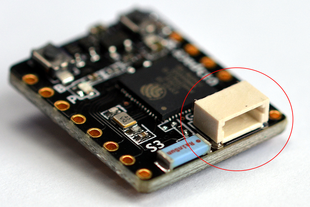
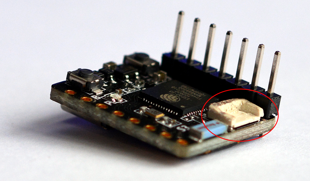
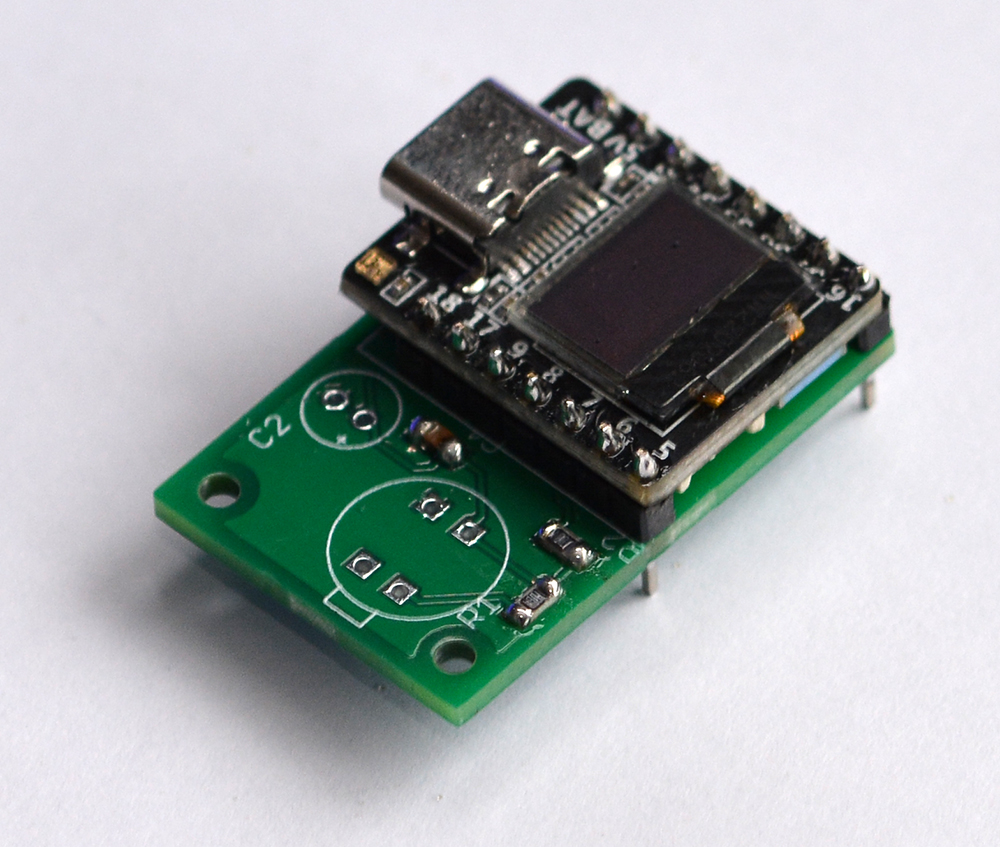
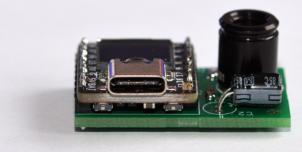
Before starting to solder the ESP32S3 board on the PCB, we must cut the white connector because it is too high and we do not need it.
Its height should not exceed the black connector as in the photo on the right.
Before you begin:
A little advice for soldering SMD components you need a magnifying glass, a fine tip of a soldering iron, and tweezers.
The tweezers are very useful, they allow you to take the resistor or the capacitor which are very small, to place them on the printed circuit but above all to hold them during the first soldering.
So, with the tweezers, place the component on the PCB (printed circuit),
on the tip of your soldering iron put some tin and do a quick solder on one side,
it’s just to fix/hold the component on the PCB.
Now that it is held by a weld, make the opposite weld properly.
Once this weld is done, go back to the first weld to do it properly too if you did not succeed the first time.
The maximum soldering time should be around 3 seconds or you risk damaging the component. If necessary, go back several times for 3 seconds maximum on a weld, letting it cool each time, rather than staying for a long time and damaging the component.
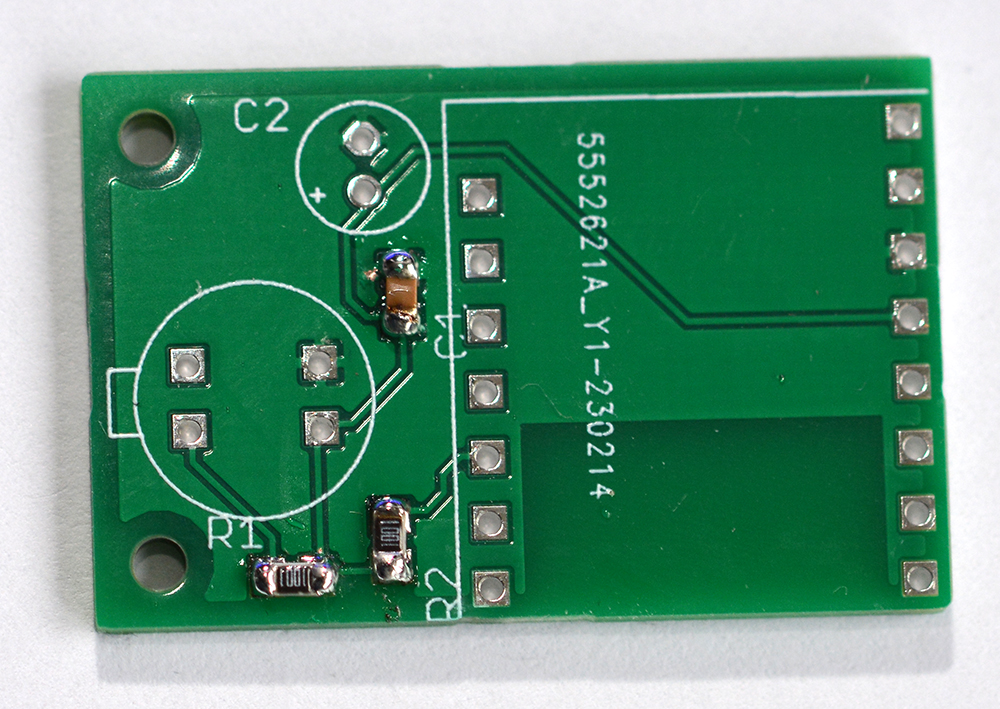
The first three components to solder are the two 1 KOhms resistors at the bottom in black (R1 and R2) and the 100nF capacitor (C1). All 3 are SMD components in 0805 format.
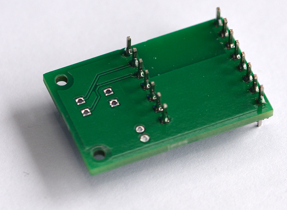
Now solder the connectors of the ESP32S3 board as well as the ESP32S3 board
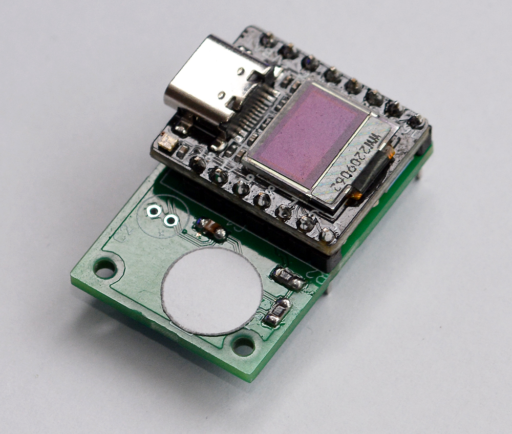
Important step!! You have to cut a piece of sheet of paper (A4 printer paper for example) and make a circle 10 mm in diameter.
This small piece of paper is to be placed between the PCB and the MLX90640 sensor because the sensor is completely metallic. This will avoid possible short circuits between the PCB and the MLX90640 sensor.
Solder the MLX90640 sensor.
ATTENTION !! There is a meaning! You can see it in the photo below, there is a small mistake that can be seen on the piece of paper that you previously cut out.
You only have the 100uF capacitor left to solder.
Also be careful here, because the capacitor has a meaning.
On the PCB (printed circuit board) there is a small “+” sign and on the capacitor there is a strip to tell you the reverse (the “-”).
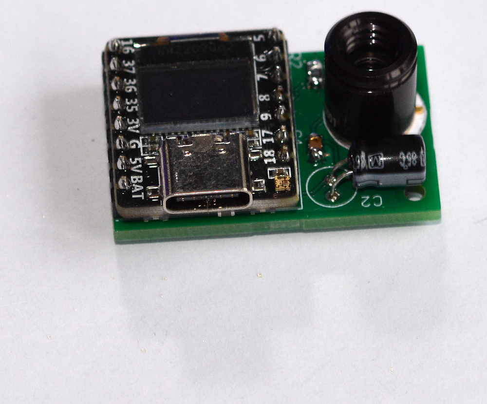
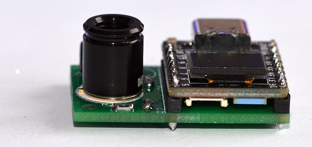
Photo of the fully soldered thermal camera module.
The thermal camera module in its case, screwed, with the USB-C adapter, ready to be used with your smartphone.

Usage :
The usage is very easy.
But, this application us two cameras, the first is the camera of your smartphone and the second is the thermal camera.
the two cameras are opposite with respect to your smartphone.
So the angle between the two cameras may be a little different.
It is therefore possible to change the image size of your smartphone in relation to the thermal camera and vice versa.
For this you can scale the images with two fingers at the same time on the screen as in the video below:

it is also possible to move the views of the cameras to correct the angles of view.
but it will not work for objects too close to the Smartphone because the two cameras are too far from each other (but there may be a solution by using a USB cable to bring them closer to each other) .
Moving is done with two fingers as below:
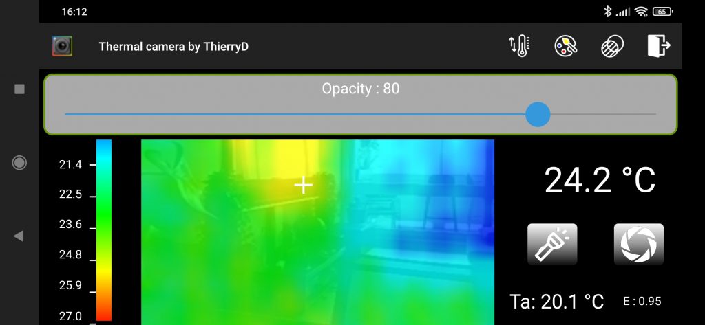
If, for example, you want to watch the thermal temperature of an object very closely, you can modify the opacity of the thermal camera so that you no longer see the camera integrated into your Smartphone.
This can also be used to better see the objects filmed by the built-in camera of your Smartphone when the visible light is weak.
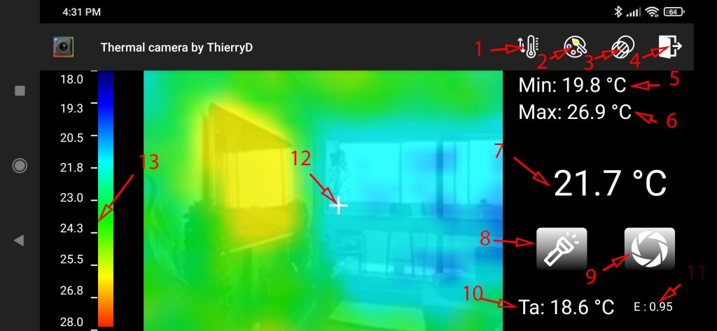
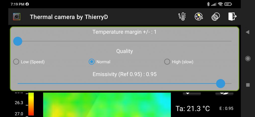
Description of interface :
- Temperature margin: This can be used when the difference between the lowest and highest temperature is small.
This makes it possible to have less color variation for deviations of a few tenths of a degree.
You can also choose the quality of the measurements:
High quality = 4 fps and 0.5 degree inaccuracy.
Low quality = 15 fps and 1.5 degree inaccuracy.
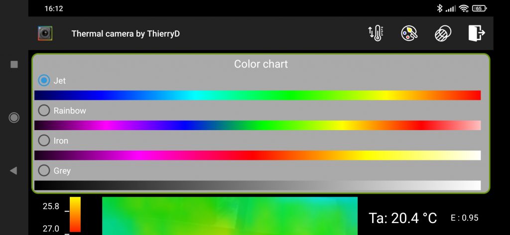
Another adjustable parameter is the emissivity of the material being measured (in most cases 0.95 is perfect). - Choice of color chart (4 charts possible)
- opacity adjustment
- Quit
- Minimum measured temperature
- Maximum measured temperature
- Temperature measured at the location of the cross (pressing the screen with the finger changes the position of the cross)
- Turns on or off the flash lamp of the Smartphone
- Take a photo (Photo in the DCIM/Camera folder of your Smartphone)
- Ambient temperature
- Thermal emissivity
- The cross indicates the place on the image where the temperature is measured
- In real time the temperature scale corresponding to the colors is updated.
This makes it easy to know what temperature corresponds to a color or vice versa.
Example of menu interfaces :
Nb: if you want, see my other project :