I suggest you make your own lightning detector for photography.
this is a DIY (Do It yourself), don’t ask me to make it for you. This cost is arround 30 Dollars.
This lightning detector has a detection cycle of 630 uS, which is excellent. Considering that your SLR camera will take several milliseconds, even tens of milliseconds to trigger and take a photo, this is more than enough.
This lightning detector can detect lightning at night but also in broad daylight. Its sensitivity in broad daylight is excellent.
Very important advice for lightning photography!!
The focus must always be set in advance and put in manual mode!!
This is what makes your SLR lose the most time, focusing can take several hundred milliseconds and therefore make you miss the lightning.
The ideal, especially if it is at night, is to put the SLR in manual mode: manual focus, speed, ISO, aperture in manual.
But, at nightfall for example, the lighting conditions change constantly, I leave my camera (SLR) in semi-automatic mode, this will make you lose a little time when triggering but generally it works (it depends on the speed of your camera).
This lightning detector is self-adjusting!!
So if the brightness varies slowly (clouds never have the same density and are constantly moving), the detector adjusts its detection threshold automatically. You set a sensitivity percentage on it, and it does the rest, even at nightfall, or when a different cloud passes.
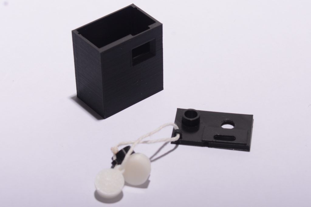
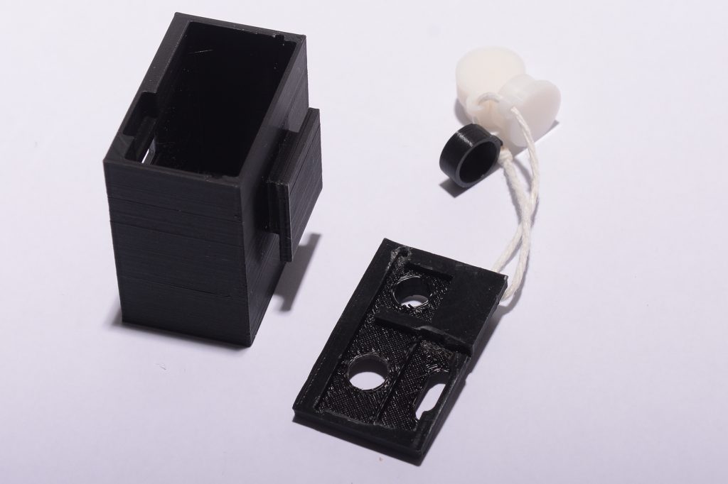
There are diffusers/attenuators that can be placed in front of the photodiode to adapt to the light conditions because the photodiode is not capable of withstanding a luminous flux of 0 to 120,000 Lux (I provide the STL files to make the case but also the diffusers in the ZIP at the bottom of the page).
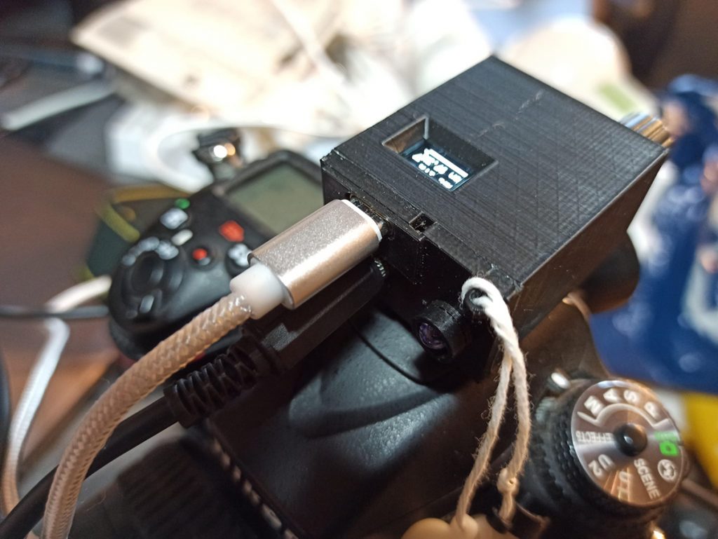
The lightning detector is equipped with a USB-C port to be powered and programmed.
You can put a transformer or a 5 Volt battery
Its manufacturing is quite simple.
You just need to know how to use a soldering iron, order the parts that I will list for you and create the case with a 3D printer.
I advise you to print this case in PETG rather than PLA to resist heat and sun, but be careful, the case is not waterproof.
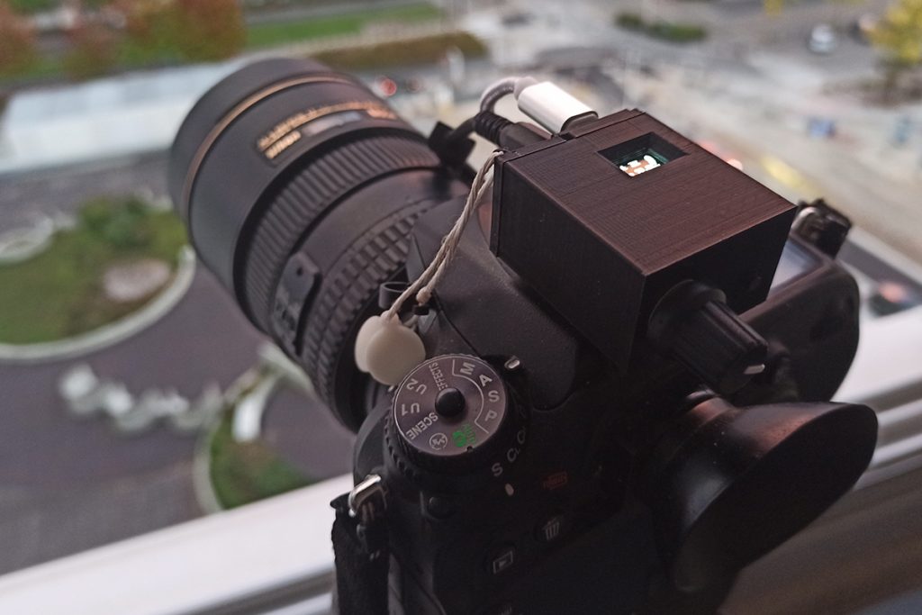
This lightning detector can be attached to the flash shoe of your SLR. The detection angle is +/- 15 degrees, which helps avoid false positives and triggering on a flash that is not in line with the lens.
some pictures of the detector mounted on the flash shoe:
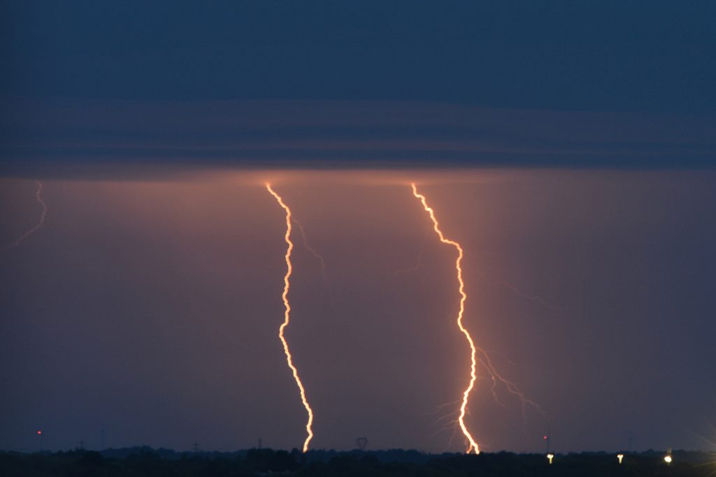
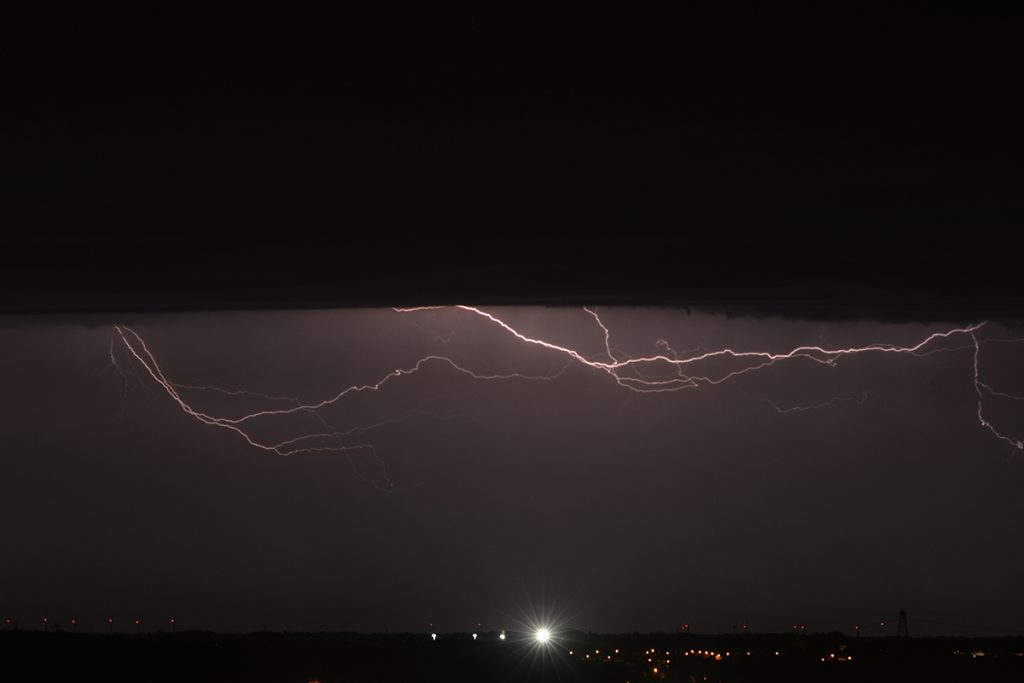
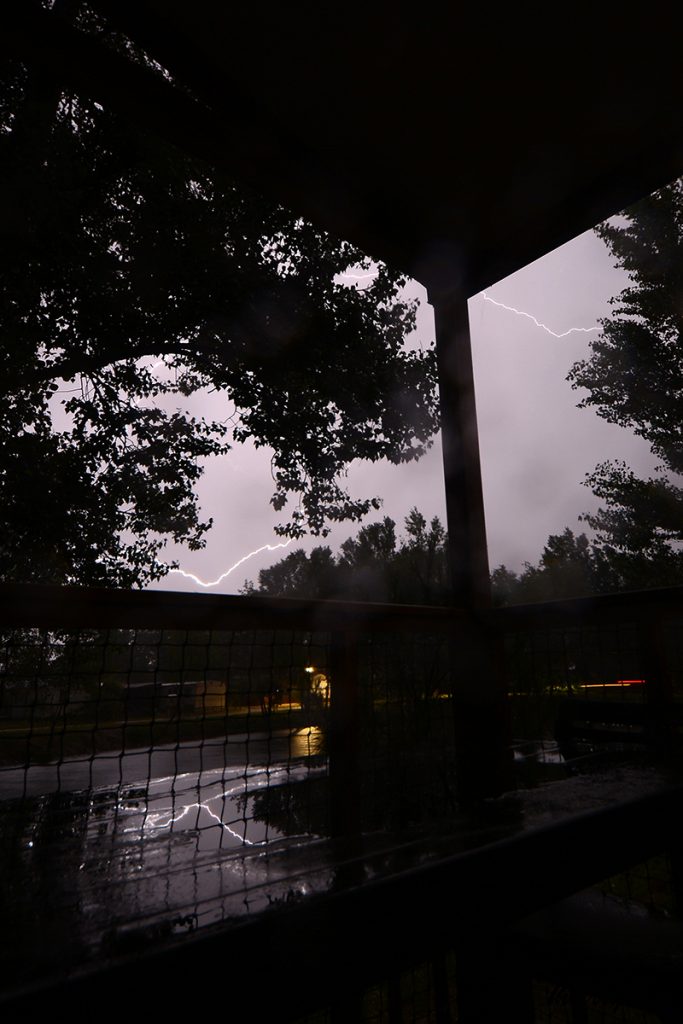
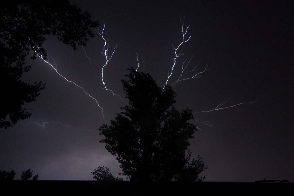
Some photos of lightning taken with the detector before getting to the heart of the matter, its manufacture:
ow let’s get down to business, its manufacture.
the list of components. I buy them on sites like Aliexpress, Alibaba, ….
- the microcontroller with its LCD: esp32 0.42 lcd S3 version => ESP32-S3-0.42LCD (around 15 Euros, the most expensive component) https://github.com/01Space/ESP32-S3-0.42OLED
- ICLT6 : An optocoupler: ILCT6 or MCT61
- P1 : potentiometer referenced B100K on AliExpress 3 pins (pins)
- right angle push button PCB 6x6x9
- SFH203 : SFH203 photodiode
- KSS1201 : active piezo buzzer (optional if you don’t want to have the BEEP during detection)
- JACK : 3.5mm stereo jack for PCB (AliExpress reference PJ-324M)
- C1 and C2 : two 100nF capacitors
- R1 and R2 : 2 220 Ohm resistors
- R3 : 1 1K Ohm resistor
- R4 : 1 resistor of 220K Ohms
- R5 : 1 resistor of 1.5M Ohms
- 40 Pin 2.54mm Female PCB Connector Strip
- cap for potentiometer (optional)
you will also have to have the printed circuit manufactured.
I have them manufactured at https://jlcpcb.com/, they are not expensive.
The manufacturing is done in batches of 5 for me of 5 Dollars including shipping costs.
I provide in the ZIP file (at the bottom of the page) containing the Eagle files of this printed circuit, a « jlcpcb gerber files.zip » file.
You can directly download the « jlcpcb gerber files.zip » file on the jlcpcb website (link GERBER FILE) to start its manufacture.
In the ZIP file there are also the STL files for 3D printing of the case and diffusers
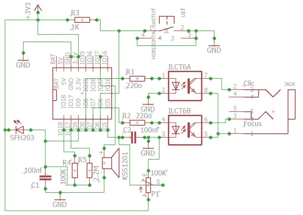
electronic circuit diagram :
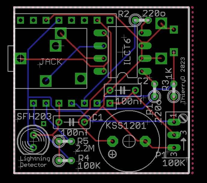
PCB :
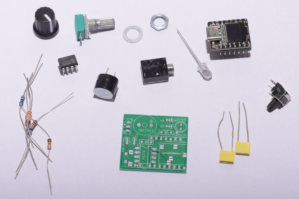
electronic components :
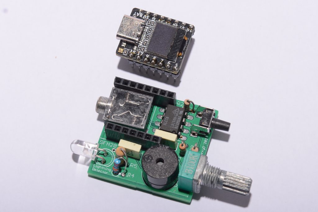
The printed circuit board mounted and soldered:
The PCB in its case :
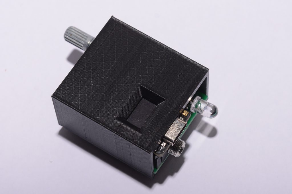
Photos of the 3D printed case :
Use :
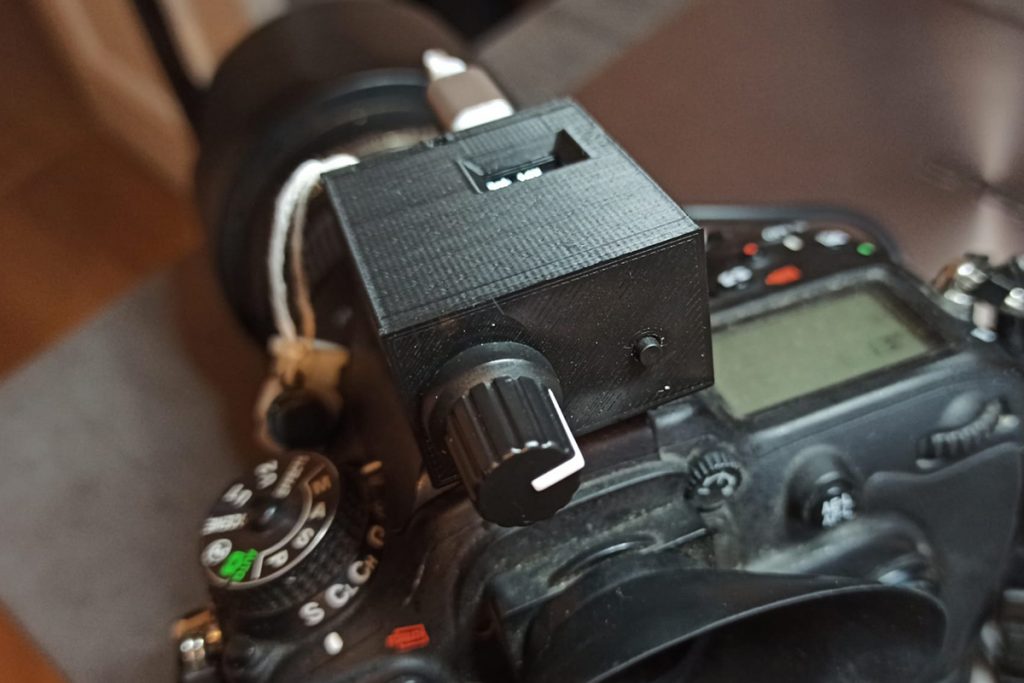
The use is quite simple since there is a button and a potentiometer.
The potentiometer allows you to adjust the detection sensitivity percentage. The closer you have a value to 100%, the more sensitive the detector will be to the slightest rapid variation in light.
This sensitivity setting is important because it allows, if necessary, to eliminate inter-cloud lightning for example.
The button allows two things.
A long press of more than 1 second allows you to deactivate or activate the buzzer.
A short press of less than 1 second allows you to switch from « no detection », « manual detection mode » and « Auto detection mode » mode.
- « no detection » mode: this allows you to make your sensitivity settings, if a lightning is detected, the LED turns green and the buzzer sounds but no photo is taken.
- « manual detection » mode, as soon as this mode is activated, the camera is locked, its focus and exposure are already calculated. the camera is ready to take the picture, this is the fastest mode.
- « Auto Detection » mode, (as I already mentioned, the focus must always be set in advance and locked in manual mode), the camera calculates its exposure and takes the picture. This mode is a little slower by a few tens of milliseconds because of the exposure calculation of your camera but is interesting at nightfall and if the lightning has a fairly long duration.
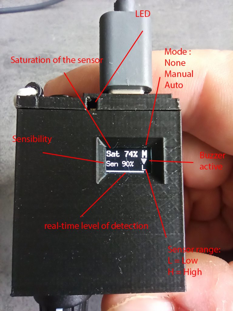
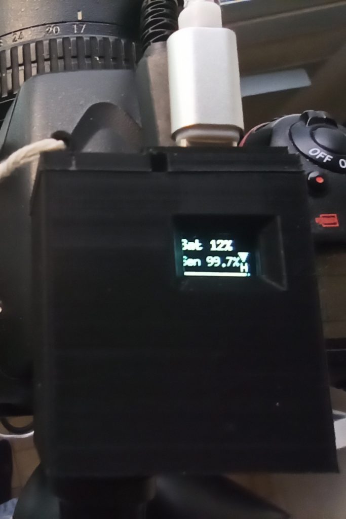
explanation of the display :
- Sensibility: This is the sensitivity level you set with the potentiometer.
- Sensor saturation: this tells you whether to put a diffuser.The SFH203 photodiode is not able to support a luminous flux of 0 to 120,000 Lux. So, if you are in full sunlight or very very clear sky, you must put the black diffuser.If you are with a very clear sky, you will have to put the thick white diffuser.If you are with a clear sky, you will have to put the thin white diffuser.At night or in very dark conditions, you will not need a diffuser.
- LED : When nothing happens the LED is off. When there is a detection it is green. If the sensor is saturated it is red.
- Mode : I talked about the detection mode just above the image. La lettre sera vide, M ou A suivant le mode.
- Buzzer Active : If the buzzer is active, the icon is visible, otherwise it is not visible.
- Sensor range : To have good sensitivity, the sensor has two rows of detection, low level or high level. This is just information, you cannot intervene on this parameter.
- Real time level detection : This progress bar varies constantly depending on the level of brightness measured and the sensitivity threshold you have set. To be very sensitive, the goal is to put this bar as far to the right as possible without ever touching the right when there is no lightning.
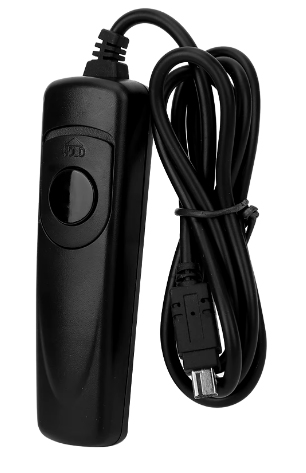
to connect this lightning detector to your camera to trigger a photo.
You will find on sites like AliExpress remote triggers corresponding to the model of your reflex (2-3 Dollars).
You will just have to open the manual shutter and cut wires, and put a 3.5mm stereo male jack to connect to the case.
Look at the image of the electronic circuit diagram, I show you how to connect GND, the FOCUS and the trigger (CLIC).
By opening the manual shutter release remote, you should have 3 wires, one common for GND, the second (the one that makes contact with GND when you press halfway) is FOCUS, and finally the last one that makes contact with the other two when you press fully is CLICK.
exemple of shutter :
So here is the link to download the ZIP file containing all the STL files for 3D printing.
The Eagle files of the printed circuit.
The gerber ZIP to have the printed circuit manufactured on the site https://jlcpcb.com/.
The .bat file and the .bin files to program the ESP32S3 microcontroller.
Nb: I do not provide the source code, only a compiled code ready to be downloaded into the ESP32S3. The source code is under Copyright.
So do not ask me for the source code ….
ZIP file link :
NB: See my other DIY
Spectrometer / flashmeter / lightmeter